
 |
| Quantity: | |
|---|---|
JH21L
WORLD
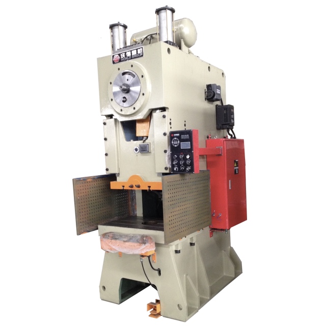
This eccentric-bush type variable stroke C-frame press is engineered for flexible, high-precision metal stamping tasks.
. Core adjustment mechanism: Stroke length is variable via a proven eccentric bush system, supporting smooth, repeatable position changes.
. Operation convenience: Manual stroke adjustment design, no complex auxiliary equipment required for quick parameter switching.
. Structural reliability: Heavy-duty C-frame steel welded body, optimized for minimal deformation under rated load.
. Control & drive system: Equipped with a full PLC control panel for automated workflow setup, matched with a maintenance-friendly dry-type pneumatic clutch.
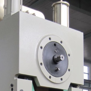 Power press stroke length adjusting mechanismThe mechanism is installed in front of the crankshaft, adjustable by manual. Motorized adjustment is optional. There is a hole for operator to check the right stroke length position. A knob for adjusting the stroke length is located on the press console. When adjusting, the pneumatic cylinder will drive the adjusting shaft out. Use a spanner to adjust the shaft to the wanted position. Turn back the stroke adjusting knob and the shaft will return back to original position. |
Dry type combined pneumatic clutch and brake
PLC central control system with HMI
Hydraulic overload protection system
Ram motorized adjusting system for 60ton and bigger sizes presses
Frequency inverter for adjustable stroke speeds
Eight faces ram gibs with bronze guide plates (25ton press is 6 faces type)
Automatic circulate thin oil lubrication system
Anti-vibration pads for press machine installation
| JH21-25L | JH21-45L | JH21-63L | JH21-80L | JH21-110L | JH21-125L | JH21-160L | JH21-200L | JH21-250L | ||||
| Capacity | kN | 250 | 450 | 630 | 800 | 1100 | 1250 | 1600 | 2000 | 2500 | ||
| Nominal Stroke | mm | 3 | 4 | 4 | 5 | 6 | 6 | 6 | 6 | 8 | ||
| Slide Stroke | mm | 10-110 | 20-120 | 10-150 | 10-150 | 10-160 | 10-160 | 16-160 | 18-180 | 21-220 | ||
| SPM | Fixed | min-1 | 100 | 80 | 70 | 60 | 50 | 50 | 40 | 35 | 30 | |
| Variable | min-1 | 80-120 | 70-90 | 60-80 | 50-70 | 40-60 | 40-60 | 35-50 | 30-40 | 25-35 | ||
| Max. Die Height | mm | 250 | 270 | 300 | 320 | 350 | 350 | 350 | 450 | 500 | ||
| Die Height Adjustment | mm | 50 | 60 | 80 | 80 | 80 | 80 | 110 | 110 | 120 | ||
| Throat Depth | mm | 210 | 230 | 300 | 300 | 350 | 350 | 380 | 390 | 420 | ||
| Between Columns | mm | 450 | 550 | 620 | 640 | 710 | 760 | 810 | 920 | 960 | ||
| Bolster | LR | mm | 700 | 810 | 900 | 1000 | 1150 | 1150 | 1300 | 1400 | 1400 | |
| FB | mm | 400 | 440 | 580 | 580 | 680 | 680 | 740 | 760 | 800 | ||
| Thk | mm | 80 | 110 | 110 | 120 | 140 | 140 | 150 | 160 | 170 | ||
| Bolster Opening | mm | φ170×20 | φ180×30 | φ200×40 | φ200×40 | φ260×50 | φ260×50 | φ300×50 | φ300×50 | φ320×50 | ||
| (Up Hole Dia.×Dpth×Low Hole Dia.) | ×φ150 | ×φ160 | ×φ180 | ×φ180 | ×φ220 | ×φ220 | ×φ260 | ×φ260 | ×φ280 | |||
| Slide Area | LR | mm | 360 | 600 | 680 | 710 | 810 | 810 | 920 | 970 | 970 | |
| FB | mm | 300 | 360 | 400 | 440 | 500 | 500 | 580 | 600 | 650 | ||
| Shank Hole | Dia. | mm | φ40 | φ40 | φ50 | φ50 | φ60 | φ60 | φ65 | φ65 | φ70 | |
| Dpth | mm | 60 | 60 | 80 | 80 | 80 | 80 | 85 | 90 | 90 | ||
| Main Motor Power | kW | 4 | 5.5 | 7.5 | 7.5 | 11 | 11 | 15 | 18.5 | 22 | ||
| Dimensions | FB | mm | 1500 | 1610 | 1680 | 1750 | 1860 | 1860 | 2250 | 2500 | 2730 | |
| LR | mm | 950 | 1170 | 1260 | 1310 | 1400 | 1450 | 1600 | 1700 | 1750 | ||
| H | mm | 2650 | 2850 | 3050 | 3150 | 3350 | 3350 | 3800 | 4200 | 4300 | ||
| Net Weight | kg | 3100 | 4350 | 6500 | 8500 | 10000 | 10700 | 14500 | 17950 | 25400 | ||




 0086 21 62828320
 0086 13817120700